
PLC Panels
How to contruct your PLC Panel
Constructing your PLC Panel
PLC Panel Construction General Arrangment Drawing
It is important to create detailed drawings for both assembly and wiring before starting construction. Enough time shoud be allocated to ensure that all design drawing are complete. Typically a Genaral Arrangement drawings will be used to construct the panel and must be drawn to accurately to scale. The Genrral Arrangement drawing will ensure that all componenets fit comfortably into the panel allowign sufficient space for hardware, trunking, glands, wire labels etc. A panel GA typically shows the followng details;
- Incomer isolator mounted on the outside of the panel to allow isolatation. These typically include a lockout mechnism.
- Circuit breakers to supply power to the 24v power supply, supply power to the PLC, supply power to field devices, supply power to the HMI, supply power to the network swithches and circuit breakers for any other devices
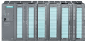
- Power supply, PLC and network swtich
- Terminals mounted close to the gland plate to land the field cables
- Fuse terminals for powering each loop.
- Relays to drive high current outputs
- Tuncking, conduit and sprague.
- Din rail layout
- Backplate mounting points.
- Panel mounting points.
- Electrical and Instrument Earth Bars
PLC Panel Construction Wiring Diagram
The wiring diagram details how each loop will be wired with all the terminals, fuses, relays, isolators or any hardware required to make the loop work. This information will demonstrate the quantities required for terminals, fuese etc. This should then be usedd as input informatio for the general arrangement drawing. A wiring diagram should contain the following information;
- The PLC terminals where the loop wiring is to be connected with the polarity of the PLC terminals, the terminal numbers, the wire colors or core numbers all clearly indicated.
- The wiring detailes of all terminals in the panel including any fuse terminals. Clearly indicating termial numbers and wire colous or core numbers dependign on the type of cable used.
- Power distribution should be shown.
- Field cable termination details should be shown.
- Earthing and grounding should be shown.
Uselful Links
Siemens Web Site