
Wiring Loops
How to wire your PLC inputs and Outputs
PLC Wiring Concepts
For each type of module, there is a reference manual which describes how the module should be used. This typicaly shows a simplified method of wiring the loops. Care should be taken to add fuses to each loop or common fuses per loops to ensure reliability and prevent damage.
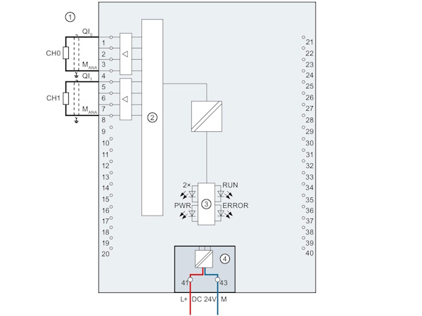
Digital Input Wiring
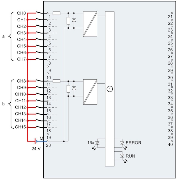
Below diagram is the recommended wiring for an input module. An external 24 volt supply is used. The 0v terminal of the power supply is connected to terminal 20 of the IO module. The 24v is then connected to one terminal of each switch being monitored. When the switch is open, no 24v is supplied to the input terminal of the input module. When the switch is closed, 24v is supplied to the input terminal. An indicator on the PLC will provide a visual confirmation of the input.
Digital Output Wiring
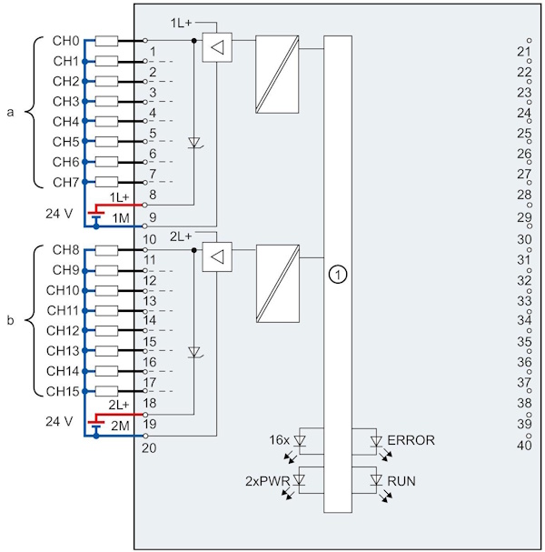
Below diagram is the recommended wiring for a digital output module. An external 24 volt supply is used. The 0v terminal of the power supply is connected to terminal 20 of the IO module. The 24v is then connected to terminal 19 of the digital ouput module. When the output is activated, 24v is supplied to the load. The other side of the load is connected to the 0v of the power supply. The 24v connected to terminal 19, passes through the ouput module, through the load and returns to the power supply completing the loop. An indicator on the PLC will provide a visual confirmation of the output.
Analog Input Wiring
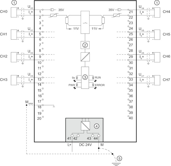
Below diagram is the recommended wiring for an analog input module. There are several different variations of analog input wiring depending on the type of transmitter. The most popular method is the 2 wire transmitter method which is described below. The various wiring methods and their use is as follows;
- 2 wire, 4-20mA Analog inputs: Used for transmitters that consume very little power and are powered by the 24v supplying the mA loop. The advantages are
- Less wiring, only 2 cores used to power the transmitter and the signal loop.
- Higher accuracy than other methods such as voltage detection. Current is the same everywhere in the loop, but voltages suffer from volt drops and are not the same through out the loop
- Best method for detecting faults. When the mA is less that approximately 3mA, this is considered a wire break and mA greater than 21mA is considered a wire short. Both conditions raise a fault alarm
- 4 wire, 4-20mA Analog inputs: Used for transmitters that consume more power than can be supplied by the mA loop. 2 wires are used for power and 2 wires for signal. In this type of input, care must be taken to check which device is powering the loop. Mostly 4 wire devices will source power for the loop and the PLC will act as a load and sink the power. The advantages are
- Higher accuracy than other methods such as voltage detection. Current is the same everywhere in the loop, but voltages suffer from volt drops and are not the same through out the loop
- Can be used for transmitters that require more power
- 2 wire, 0-10v Analog inputs: Used for transmitters that provide a voltage ouput. This type of analog input is not very common due to the requirement for calibration to compensate for volt drops caused by wiring and terminals.
- Lower accuracy than other methods.
- Simplest type of loop, easy to fault find with any multimeter
Analog Output Wiring
There are generally 2 types of analog outputs, 4-20mA and 0-10v. 4-20mA outputs are the most common and recommended output for accuracy and fault detection.
An external 24 volt supply is used, but the loop is powered internally by the module. The 0v terminal of the power supply is connected to terminal 43 of the IO module. The 24v is connected to terminal 41 of the IO module. The loop is powered by the module positive terminal with 24v. The module regulates the current 4-20mA flowing through the loop.
Uselful Links
Siemens Web Site